

Why are my Cisco Access Points not transmitting at maximum allowed EIRP?
When looking into my WLC controlled APs’ cli, I noticed that even with the highest configured TX power (Level 1 in the WLC) and several external antenna options they would never Transmit @ max. EIRP for my Regulatory domain following the simple EIRP formula of EIRP = TX Power (dBm) + Antenna Gain (dBi) - Insertion Loss (dB).
Max. EIRP for Belgium (ETSI)

If for example (using previous formula), the max. TX Power would be 25dBm, the Antenna Gain 5dBi and the cable/connector Loss 0dB, then taking the max. allowed EIRP for ETSI 5GHz U-NII-2ext. into account (30dBm or 1000mW), the formula would be: 25dBm + 5dBi = 30dBm (we don’t care for insertion loss for this example due to fixed antenna gains (cable/connector loss is already included).
So in short, I would expect that the AP’s EIRP would be 30dBm @ the exit point of the antenna.
More technically speaking, it would be 19dBm TX Power/antenna combined to 25dBm (4x4 MIMO) Total Power for our test AP (AIR-AP1572EAC-E-K9), the principle is that the more antennas (radio chains) you add, the higher the combined gain and this will needs to be subtracted from the TX Power per radio chain. You can calculate this with following formula: 10 x log10(number of antennas).
For example:
2 antennas >> 10 x log10(2) = 3,0103 >> 3dB gain
3 antennas >> 10 x log10(3) = 4,7712 >> 4,8dB gain
4 antennas >> 10 x log10(4) = 6,0206 >> 6dB gain
25dBm Total Power - 6dB = 19dBm TX power/radio chain

Now, to make it more complex, this is without standardised TX beamforming taken into account, when this feature is used, the max. combined signal strength at the receiver would be higher then without TX beamforming enabled. How much exactly, will once more depend on the number of radio chains.
So in our case with 4 antennas, we need to subtract another 6dB from our TX Power/radio chain budget.
19dBm TX power/radio chain - 6dB TX beamforming gain = 13dBm TX power/radio chain
13dBm TX power/radio chain + 6dB gain = 19dBm Total Power

But wait, in both tabels, an antenna gain of only 4dBi is presumed and the max. TX power we get is 25dBm so we will only transmit @ 29dBm EIRP.
I have an idea, let’s change the antenna(s) to 5dBi, that surely would solve our issue, because 25dBm + 5dBi = 30dBm, or is it not that simple?
Let’s have a closer look at the power chart for a 5dBi antenna.

Oh my, we are still not getting our 30dBm, because the Power was lowered by another 1dB.
So why are we never reaching our max. EIRP of 30dBm?
Let’s take a step back and see what the max. allowed TX power is for 20MHz wide 5GHz channels on our test AP.

Wow, now the max. Power allowed is only 24dBm , this is getting very confusing 🙂. Let’s have a closer inspection inside the APs’ cli and test what happens with the max. Power level (Level 1) and EIRP in several configuration examples (choosing different antenna gains in the WLC config).
Note 1*: The transmit power level is assigned an integer value instead of a value in mW or dBm. The integer corresponds to a power level that varies depending on the regulatory domain in which the access points are deployed. The number of available power levels varies based on the access point model. However, power level 1 is always the maximum power level allowed per country code setting, with each successive power level representing 50% of the previous power level (-3dB). Below a chart for our test AP with a max. of 23dBm TX power, we are getting closer to solving this riddle 🙂.

Note 2*: For all my configuration examples, the power level configured will be @ Level Index 1 and the configured frequency will remain @ 5540MHz (Ch 108).
The only thing that will change is the antenna gains.
AIR-AP1572EAC-E-K9 Configuration Examples
Used Cisco cli command:
- Cisco AP > "show controllers dot11Radio 1" (5GHz radio)
mW to dBm conversion formula:
- 10 x log10 (mW) = dBm
Configuration Example 1
Carrier Set: Belgium (BE) (-E)
Uniform Spreading Required: Yes
Configured Frequency: 5540 MHz Channel 108 (DFS enabled)
Configured TxPower: 20 dBm (Level Index 1) Allowed Power Levels: 20 17 14 11 8 dBm Allowed Client Power Levels: 20 17 14 11 8 dBm Antenna: Rx[a b c d ] ………………………………………..Tx[a b c d ofdm all]
External Gain [Allowed 8, In Use 14] (dBi x 2) 10, In Use 14] (dBi x 2) 14, In Use 14] (dBi x 2) 16, In Use 14] (dBi x 2) 26, In Use 14] (dBi x 2) 28, In Use 14] (dBi x 2), Reported 14, Configured 14, In Use 14] (dBi x 2)
So, what did we learn from this output?
- The channel configured is 108 (5540 MHz) which is located in the U-NII-2ext band.
- We statically configured the External antenna gain to 7dBi (14 increments of 0,5dBi).
- The AP auto chose the TX power level of 20 dBm (when configured on level index 1).
- Like previously mentioned, the AP uses 3dBm power increments.
- Remember our EIRP formula? EIRP = TX Power (dBm) + Antenna Gain (dBi) , let’s apply it here: 20dBm + 7dBi = 27dBm EIRP
Why did the AP not choose 23dBm? It’s all RF math baby 🙂, the way It works is that the AP uses mW to calculate the EIRP and not dBm, so we need to convert our Power levels to mW first. You will see tables like the one below to convert dBm to mW and vice versa, but those tables are not accurate though. Why exactely? Because dBm is an Absolute/logarithmic power value and mW is an Absolute/linear value.
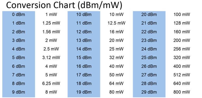

Let’s apply the mW to dBm conversion formula and first calculate the EIRP for 23dBm (200mW) and then 20dBm (100mW) TX Power.
TX Power = 10 x log10 (200mW) = 23,0103dBm
EIRP = 23,0103dBm + 7dBi = 30,0103dBm
TX Power = 10 x log10 (100mW) = 20dBm
EIRP = 20dBm + 7dBi = 27dBm
So here lies the answer: 200mW was not chosen because this would result in a dBm value of 23,0103 and when adding this to the antenna gain of 7dBi would result in an EIRP of 30,0103dBm, which is higher then the max. allowed 30dBm for ETSI and therefore is rejected. The AP will step down 3dB to the next available power level which in this case is 20dBm (Level 1) and finally results in an EIRP of 27dBm which is accepted.
Configuration Example 2
In this second example, the antenna gain was configured statically to 4dBi.
Carrier Set: Belgium (BE) (-E) Uniform Spreading Required: Yes
Configured Frequency: 5540 MHz Channel 108 (DFS enabled)
Configured TxPower: 23 dBm (Level Index 1) Allowed Power Levels: 23 20 17 14 11 8 dBm Allowed Client Power Levels: 23 20 17 14 11 8 dBm Antenna: Rx[a b c d ] ................................Tx[a b c d ofdm all]
External Gain [Allowed 8, In Use 8] (dBi x 2) 10, In Use 8] (dBi x 2) 14, In Use 8] (dBi x 2) 16, In Use 8] (dBi x 2) 26, In Use 8] (dBi x 2) 28, In Use 8] (dBi x 2), Reported 8, Configured 8, In Use 8] (dBi x 2)
TX Power = 10 x log10 (200mW) = 23,0103dBm EIRP = 23,0103dBm + 4dBi = 27,0103dBm
Configuration Example 3
In this last example, the antenna gain was configured statically to 0dBi and therefore the APs’ automatic antenna detection kicked in and chose 4dBi as the gain. Keep in mind that automatic antenna detection may be inaccurate though so use this with caution.
Carrier Set: Belgium (BE) (-E) Uniform Spreading Required: Yes
Configured Frequency: 5540 MHz Channel 108 (DFS enabled)
Configured TxPower: 23 dBm (Level Index 1) Allowed Power Levels: 23 20 17 14 11 8 dBm Allowed Client Power Levels: 23 20 17 14 11 8 dBm Antenna: Rx[a b c d ] ................................Tx[a b c d ofdm all]
External Gain [Allowed 8, In Use 8] (dBi x 2) 10, In Use 8] (dBi x 2) 14, In Use 8] (dBi x 2) 16, In Use 8] (dBi x 2) 26, In Use 8] (dBi x 2) 28, In Use 8] (dBi x 2), Reported 0, Configured 0, In Use 8] (dBi x 2)
TX power = 10 x log10 (200mW) = 23,0103dBm EIRP = 23,0103dBm + 4dBi = 27,0103dBm
I hope this will be a useful post for all Cisco guys/girls out there and please do not hesitate to comment.
Best regards and hopefully we meet again soon @ my next one.
-The End-
